

Infrastructure
Data centre power and connectivity: the IT infrastructure layer that M&E contractors do not cover
· 9 min read
Data centre power and connectivity at the IT layer covers the distribution, installation and management of power from the floor-level PDU to each device in the rack, and the installation of cross-connects and patch leads connecting your equipment to the facility network. This is distinct from M&E electrical contracting, which installs busways, switchgear and floor-level PDUs. M&E contractors bring power to the rack; IT-layer work handles everything from the PDU socket onward. Both disciplines are needed at different project stages, and confusing one for the other produces scoping gaps.
The power chain from utility to socket
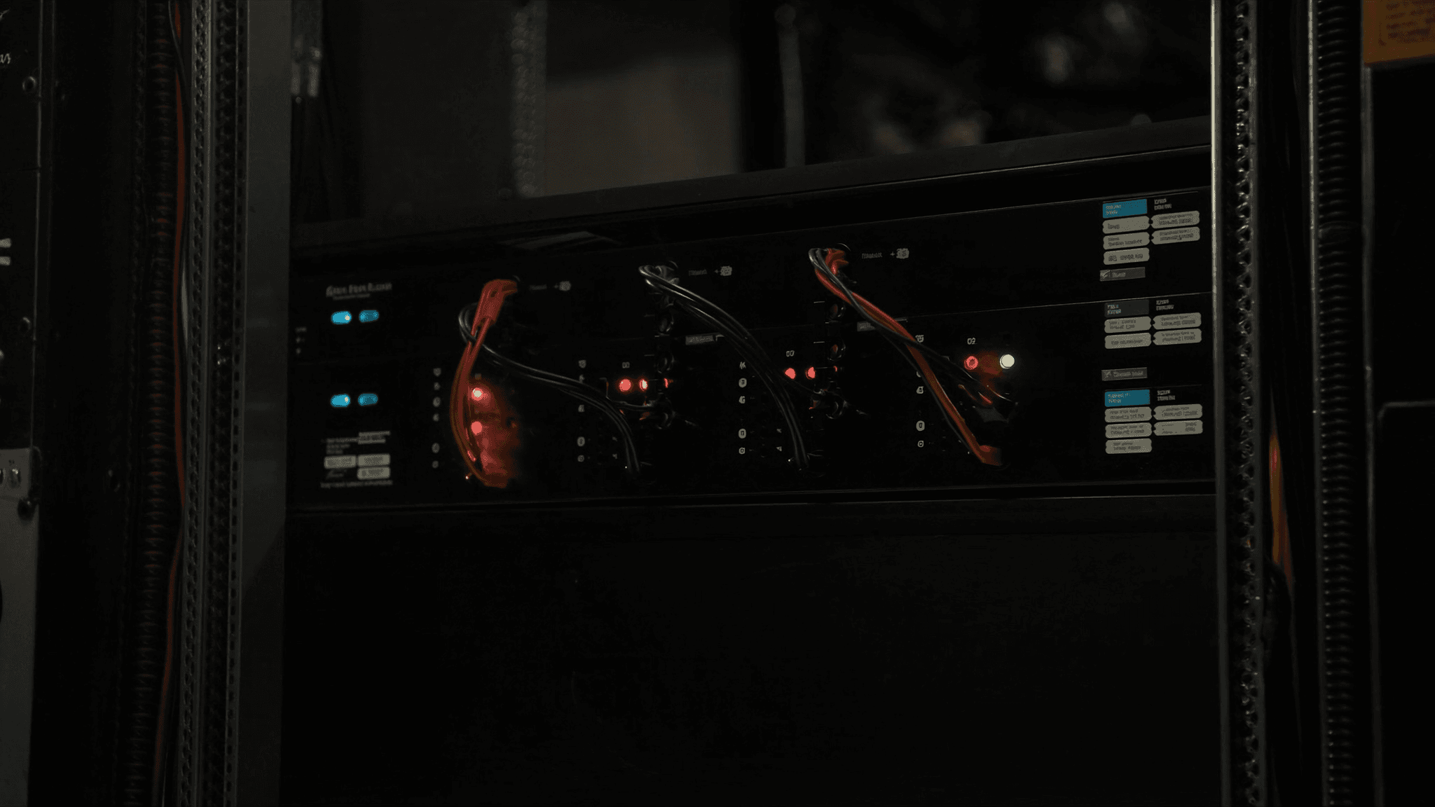
Power in a colocation data centre follows a chain with multiple tiers. The facility's incoming utility supply feeds the primary switchgear and from there to the UPS systems. The UPS output feeds the busway or floor-level power distribution units. The PDUs distribute power to individual outlets, and from those outlets, power leads run to each device in the rack. Redundancy is designed into the chain at each tier: dual utility feeds, N+1 or 2N UPS, separate A-feed and B-feed busways. The effectiveness of that redundancy at the device level depends on how the IT team connects their equipment, not on the facility's M&E design.
PDU types: metered, switched and outlet-level monitoring
Rack PDUs come in several types, each offering a different level of visibility and control. A basic PDU distributes power to multiple outlets with no monitoring capability. A metered PDU measures the total current draw at the unit level and makes it available via a network management port. A switched PDU allows individual outlets to be powered on or off remotely. An outlet-level metered PDU measures the current draw at each individual outlet and reports it via the network, allowing engineers to see the draw of each device without a physical site visit.
| Feature | Outlet-level monitoring | Remote outlet switching | Best for |
|---|---|---|---|
| Basic PDU | No | No | Non-critical equipment where monitoring is not required |
| Metered PDU (unit-level) | No (unit level only) | No | Capacity planning with low per-unit cost |
| Switched PDU | No | Yes | Remote power cycling where monitoring is not needed |
| Outlet-level metered PDU | Yes | No | Power audit and capacity planning without site visits |
| Intelligent (switched + outlet metered) | Yes | Yes | High-availability environments requiring full remote control |
A and B feeds: the trap that bypasses the redundancy
Verifying genuine A and B independence requires tracing each feed from the device back through the PDU to the busway and from the busway back to the UPS output. This cannot be confirmed from the rack alone: it requires either the facility operator's power distribution diagram or a physical trace. Most facilities will confirm the independence of feeds on request, and many include it in their customer portal.
Circuit sizing: nameplate versus measured draw
Power circuits in a data centre are sized to their nameplate capacity, which is the maximum rated draw of the equipment connected to them. In practice, equipment rarely draws its nameplate maximum: a server rated at 800W may draw 320W at typical load. Planning circuits entirely from nameplate figures produces racks with a large headroom gap, which is wasteful in a colocation environment where power is billed by committed draw or measured consumption. Measuring actual draw during steady-state operation, using outlet-level PDU monitoring or a clamp meter, allows circuits to be correctly sized for actual use rather than theoretical maximum.
Cross-connects: what they are and what the process involves
A cross-connect is a physical cable installed by the data centre facility's own cabling team that connects your cabinet to another cabinet in the same facility, to the facility's meet-me room or to a specific carrier's network access point. Cross-connects are ordered through the facility operator and typically take four to eight weeks to provision. The process involves specifying the source and destination patch panel positions, the cable type (copper, single-mode fibre or multimode fibre), the speed and the demarcation point where your responsibility begins.
Power capacity planning and headroom
Most colocation facilities provide a committed power allocation per cabinet, typically measured in kilowatts. The committed allocation determines the cooling and power infrastructure the facility provides for that cabinet. Exceeding the committed allocation can cause thermal events and breaker trips; maintaining excessive headroom between the committed and actual draw is inefficient. Capacity planning requires measuring the current draw accurately, modelling the growth trajectory of the workload and confirming the committed allocation matches the expected peak draw with a defined headroom margin, typically 20 to 30 percent above the measured peak.
IT-layer connectivity: patch leads, cross-connects and breakout
Connectivity work within the rack and between the cabinet and the facility patch panels is IT-layer work, distinct from M&E. It includes installing and dressing patch leads from servers to top-of-rack switches, running fibre from the rack to the facility's structured cabling distribution frame, and installing the MPO or LC connectors at the termination points. These tasks require engineers experienced in data centre cabling standards, not M&E electrical certification. The scoping distinction matters because the engineers who install a busway are not the engineers who patch a server into a top-of-rack switch.