

Infrastructure
Rack and stack in UK data centres: what's involved and when to outsource
· 10 min read
Rack and stack is the physical installation of servers, storage and network hardware into data centre cabinets, following an agreed elevation drawing and working to a cable management plan. A completed rack and stack delivers every device mounted, labelled at both ends, connected to independent A and B power feeds, verified as network-reachable, and photographed for the as-built record. Most project overruns trace to the preparation phase rather than the physical day: the elevation drawing, rail kit logistics and power allocation are where rack-and-stack projects succeed or fail.
What rack and stack covers
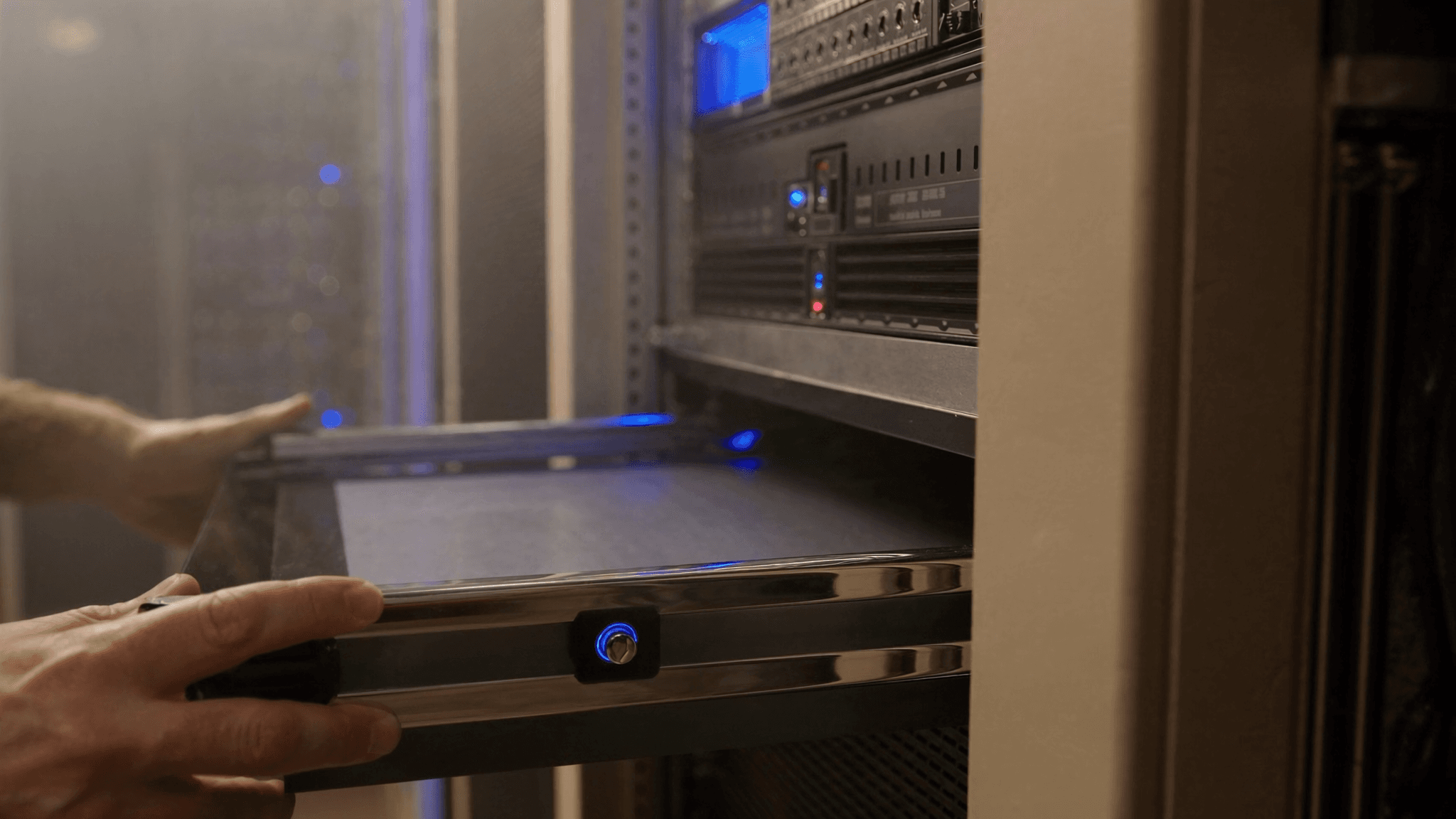
The term is often used to mean simply placing hardware into a cabinet, but a professional rack and stack is a sequence of distinct tasks. The engineer arrives with an elevation drawing showing each device, its rack unit position, its rail kit type and its power requirements. They unbox, inspect and mount each device in the specified position, run structured cabling and power connections to the correct ports, apply labelling at both ends of every cable, verify each device powers up and is reachable, and produce an as-built record before leaving site.
- Physical inspection and unboxing, with any transit damage recorded before installation begins
- Rail kit installation and hardware mounting to the elevation drawing
- Structured copper and fibre cabling to the agreed patch plan
- Power connection to independent A and B feeds at the correct amperage
- End-to-end cable labelling to the agreed naming convention
- Power-on verification and network reachability check for each device
- As-built photography and elevation diagram update before the engineer leaves site
The elevation drawing: why it drives everything
An elevation drawing, sometimes called a build sheet, is a rack diagram showing each device by position, unit height, model and power specification. It exists before the engineer arrives and is the single source of truth for the physical work. Without one, the engineer makes decisions on the data centre floor that should have been made in the office: which device goes where, how the cabling routes, which ports connect to which. Those decisions take time under pressure.
A complete elevation drawing specifies: the rack unit position for each device, the rail kit model required, the cable plan showing source and destination port for each cable, the power allocation showing A-feed and B-feed circuit identifiers and their amperage budget, and the labelling convention for cables and ports. If the drawing is accurate, a competent engineer can complete the work without needing to make any significant decisions on site.
Rail kits: the detail that delays most projects
Rail kits are the sliding or fixed brackets that mount servers and storage devices in a cabinet. They are model-specific: rails for a Dell PowerEdge R750 will not fit an HPE ProLiant DL380. The most common single cause of rack-and-stack delays is an engineer arriving at site without the correct rail kits, or with rail kits that are the wrong revision for the rack depth.
Cable management: copper, fibre and power
Within a rack, cables run from device ports to patch panels or directly to switch ports. The quality of the cable management affects every future session in that rack: poor routing slows future changes, creates risk of accidental disconnection and makes fault-finding harder. A professional rack and stack follows a cabling standard, maintains consistent bend radii, uses velcro ties rather than zip ties on copper and fibre, and labels every cable at both ends.
| Feature | Bend radius minimum | Fastening method | Label format |
|---|---|---|---|
| Cat6A copper | 8 x cable diameter (typically 48mm) | Velcro hook-and-loop ties | Both ends: port to port |
| OM4 multimode fibre | 30mm at any point | Soft velcro ties only | Both ends: port to port |
| OS2 single-mode fibre | 30mm at any point | Soft velcro ties only | Both ends: port to port |
| Power (C13/C14, C19/C20) | No minimum, but dress neatly | Velcro ties or cable clips | Circuit identifier at device end |
A and B power feeds: what dual redundancy actually requires
Most servers and storage devices have two power supplies. The reason is redundancy: if one power circuit fails, the device stays online on the other. This only works if the two power supplies are connected to two independent circuits, typically an A-feed and a B-feed backed by separate UPS systems. A rack and stack that connects both power supplies to the same circuit delivers no redundancy, regardless of whether the device has two power supplies.
The power allocation plan should specify before the engineer arrives: the A-feed circuit identifier serving the rack, the B-feed circuit identifier, the total amperage available on each feed and the amperage consumed by each device. Without this, the engineer cannot verify that the power draw is within circuit capacity, and cannot confirm the A and B feeds are genuinely independent.
Labelling: the task most teams regret skipping
Every cable in a rack should be labelled at both ends, showing the source port identifier and the destination port identifier. The label should match the cable plan so the as-built record, the physical label and the CMDB entry all agree. Unlabelled or mislabelled cables slow down every future change in that rack, because the engineer must trace each cable manually before touching it.
The labelling convention should be agreed before the engineer arrives, not invented on the day. A common scheme is port-to-port labelling: each label reads source port to destination port, for example 'SRV01-PSU1 > A-PDU-12'. The specific convention used matters less than its being consistent across every rack in the estate.
Documentation to receive after the work
- Updated elevation diagram reflecting the final installation, including any changes from the original plan
- Front and rear photographs of each rack
- Cable schedule listing every cable with its source port, destination port and label
- Power audit showing the measured draw from each PDU and the available headroom per circuit
- Any punch-list items not completed, with the reason and agreed resolution date
When to use an independent smart hands provider
Internal teams handle rack and stack well when the work is in their primary data centre, the hardware is familiar and the schedule is flexible. The case for an independent provider grows when the rack is in a remote data centre the team cannot easily reach, the work needs to happen out of hours, the project spans multiple sites or the team lacks experience with the specific hardware being installed. A provider with established access to the relevant facilities eliminates the access management overhead and removes the travel cost and time from the project timeline.