

Infrastructure
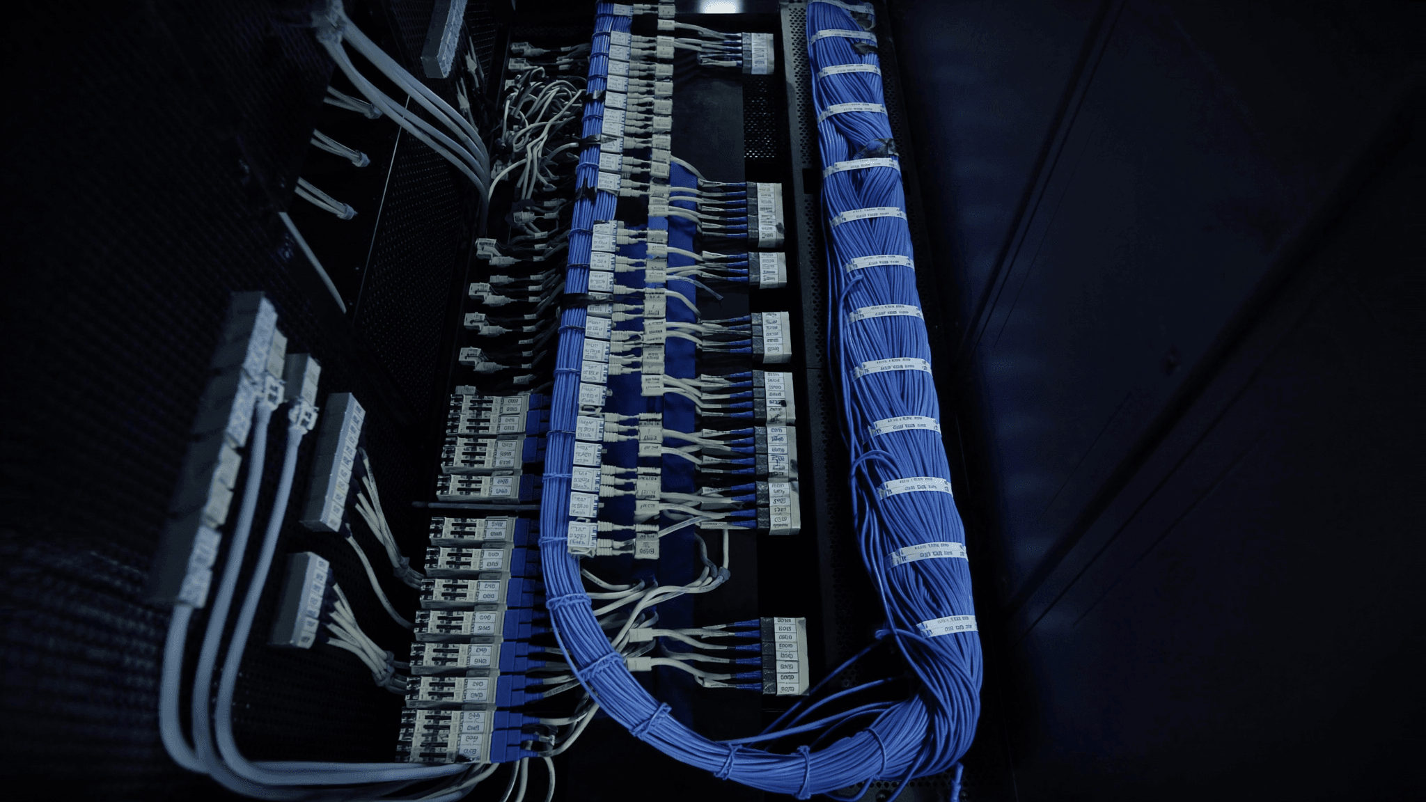
Data centre structured cabling: standards, cable types and what a professional installation covers
· 10 min read
Data centre structured cabling is the permanent infrastructure layer of copper and fibre connecting active equipment to patch panels, distribution frames and switches. TIA-942 and ISO/IEC 11801 define performance classes, maximum channel lengths and the test standards a completed installation must pass. The practical difference between a cabling system that causes problems and one that does not is almost always in the installation: bend radius violations, poor terminations, incorrect labelling and skipped test documentation account for most faults found at commissioning.
Standards that apply to data centre structured cabling
Two standards govern data centre structured cabling in the UK. TIA-942 is the US standard published by the Telecommunications Industry Association, widely adopted internationally. ISO/IEC 11801 is the international standard (published by the International Organization for Standardization and the International Electrotechnical Commission), with BS EN 50173-5 as its European implementation for data centres. The two standards overlap considerably. Most UK installers reference ISO/IEC 11801 and BS EN 50173, with TIA-942 cited as a cross-reference where it is more specific.
The standards define: performance classes for copper channels (Class D through Class FA, corresponding to Cat5e through Cat8), performance classes for fibre channels (OM1 through OM5 for multimode, OS1 and OS2 for single-mode), maximum channel lengths for each class and speed combination, connector performance requirements, and the test parameters and pass/fail thresholds that a OTDR measurement or Fluke certification test must meet.
Horizontal versus backbone cabling
Structured cabling in a data centre is divided into horizontal and backbone sections. Horizontal cabling runs from the zone distribution area or floor distributor to each cabinet row or individual cabinet. Backbone cabling connects the main distributor (typically in the main distribution area) to the intermediate and horizontal distributors. The physical separation matters because the standards set different channel length limits for each, and a cabling system designed without that distinction will often fail tests when the horizontal and backbone segments are combined into one longer channel.
Copper cable grades: Cat6A versus Cat8
The choice between cable grades in a data centre is usually between Cat6A and Cat8. Cat6A (Class EA, ISO/IEC 11801) is the minimum grade specified for 10GBASE-T over 100m and is the most common choice for horizontal cabling in UK data centres installed since 2010. Cat8 (Class I and Class II) is a newer standard, supporting 25GBASE-T and 40GBASE-T over shorter distances (30m for Class I and 30m for Class II). Cat8 is relevant for top-of-rack switch connections where the horizontal run is short and the speed requirement is high.
| Feature | Maximum channel length | Supported speeds | Typical use |
|---|---|---|---|
| Cat5e (Class D) | 100m | Up to 1GBASE-T | Legacy; not recommended for new installs |
| Cat6 (Class E) | 100m | Up to 1GBASE-T (10G to 55m) | Legacy; not recommended for new installs |
| Cat6A (Class EA) | 100m | Up to 10GBASE-T | Standard for new UK data centre installs |
| Cat8 (Class I/II) | 30m | Up to 40GBASE-T | Top-of-rack switch to server, short runs only |
Fibre in the data centre: OM4, OM5 and OS2
Fibre cabling in a data centre falls into two categories: multimode for short-distance applications and single-mode for longer runs and DWDM applications. OM4 is the current standard for multimode fibre in UK data centres, supporting 100GBASE-SR4 to 150m and 400GBASE-SR4 to 100m using VCSEL-based transceivers. OM5 extends the reach of shorter multimode links for some shortwave wavelength division multiplexing (SWDM) applications, but the incremental benefit over OM4 is modest for most data centre deployments. OS2 (single-mode) is the correct choice for any run longer than the multimode channel limits, for any link that needs to carry DWDM traffic and for any infrastructure that needs to last more than one equipment generation.
Cable management and containment
Cabling standards specify minimum bend radii, and those radii are regularly violated in data centres where cabling is installed without a containment plan. For Cat6A, the minimum bend radius is 8 x the cable diameter, typically around 48mm. For fibre (all types), the minimum bend radius at any point in the run is 30mm. A fibre cable bent to 20mm at the edge of a cable tray will pass through testing at installation but will degrade over time as the glass core is stressed at the bend point.
Testing and certification
Every structured cabling installation in a data centre should be tested and certified. For copper, the standard tool is a Fluke DSX-8000 or equivalent, running the relevant TSB-568 or ISO/IEC 11801 test suite for the cable grade. For fibre, testing includes insertion loss measured by an OLTS (optical loss test set) and OTDR (optical time-domain reflectometer) trace to show the loss budget at each connector and verify there are no splice events or reflections that indicate a damaged section.
The test report produced at completion should include: the test suite used, the cable grade tested against, the pass/fail result for each link, the measured parameters for each link and the date of test. This report is the evidence base for any warranty claim and for any future fault diagnosis. An installation without a test report has no documented performance baseline.
Labelling and documentation
A labelling scheme for structured cabling needs to be defined before installation begins. The most useful schemes use port-to-port labelling on every cable, meaning each label at both ends of the cable shows the source port identifier and the destination port identifier. When combined with a cable schedule (a spreadsheet or CMDB record listing every cable with its source, destination, cable type and label), this allows any engineer to identify a cable without tracing it, understand the connectivity without a drawing and make changes without risk of disconnection.
Signs of a poor structured cabling installation
- Cables bundled with zip ties rather than velcro: zip ties compress the cable and degrade performance over time
- Fibre runs with visible bends at the patch panel entry: indicates the 30mm bend radius has not been maintained
- Unlabelled or partially labelled cables: makes future changes slow and risky
- No test report or OTDR traces: no performance baseline and no warranty evidence
- Mixed cable grades in the same channel: for example, Cat6A horizontal cable terminated at a Cat6 patch panel
- Cables not dressed through cable managers: a rack full of loose cables indicates no cable management plan was followed